Audio Technica PRO24-CM stereo microphone modifications
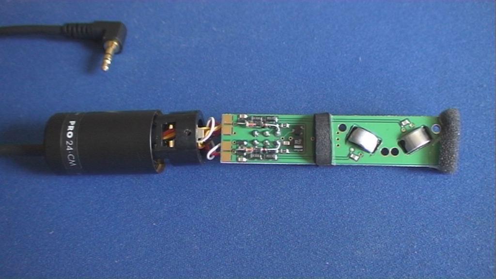
The "German" ModsOnly relevant for battery-free operation with plug-in power None of these modifications change the gain of the microphone when it is running on an internal battery To access the board: Unscrew the rear section of the housing to expose the battery compartment Slide the rear section along the cable to get it out of the way Remove the screw on the bottom and the 2 screws holding the switch Press the switch lightly and carefully begin to push the board out of the housing using the switch Do not pull the board using the battery compartment because a wire could be ripped When the board is exposed, carefully pull it out of the housing Keep the soldering iron and its heat away from the round foam because it will shrink You can damage the microphone if you are not careful, do not solder well, or if you lack the proper equipment No warranty of any kind. Use this information at your own risk
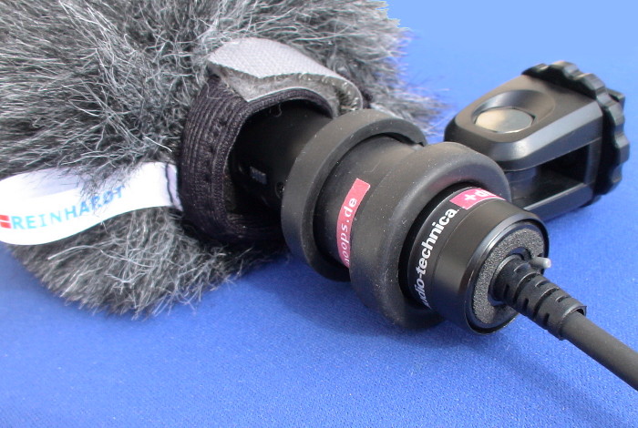
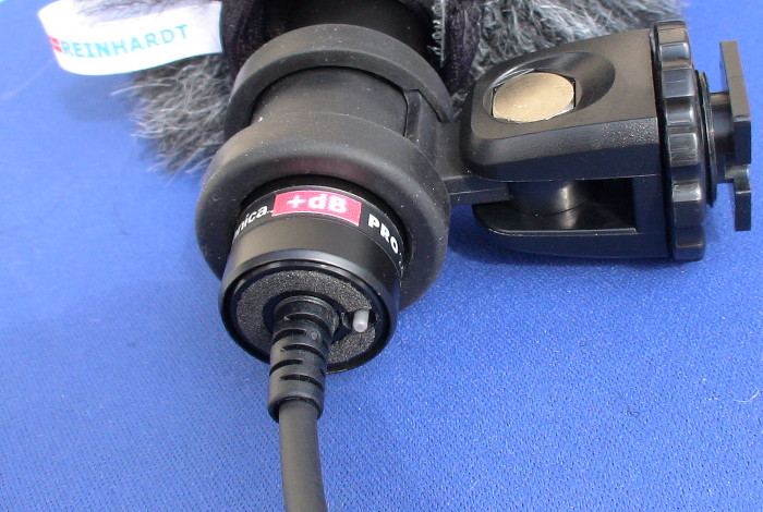
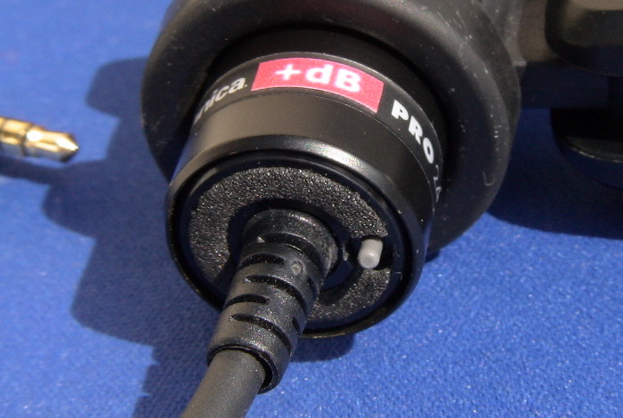
The above photos show the Audio Technica PRO24-CM microphone with an additional gain selection switch next to the cable. It is wearing a windsock from Reinhardt of Denmark, who offers handmade quality windshields that are not expensive. Their windsock 50-70 fits over the foam windshield that comes with this microphone. Its fur length matches the height of the microphone in the shoe bracket, so the fur does not get into the lens.
Higher output level in battery-free operation with germanium diodes to reduce the voltage drop of the plug-in power from a Sony camcorder by about 0.4V.This was the first change I made to raise the weak signal levels in battery free operation, without cutting any traces or removing any components. However, I am now using a different and much more effective modification, which is difficult but achieves full output levels and allows adjusting the gain. It is shown in the next section, below this modification.
1.1 Background information and details
My Sony DV camcorders do not provide any manual gain or level settings for the microphone input. The microphone plug-in power delivered by the camcorders is about 2.5V, which is internally fed through 6.8K resistors to the left and right connections in the microphone jack. The forward voltage drop across the diodes in the Audio Technica microphone circuit decrease the voltage to the capsules.
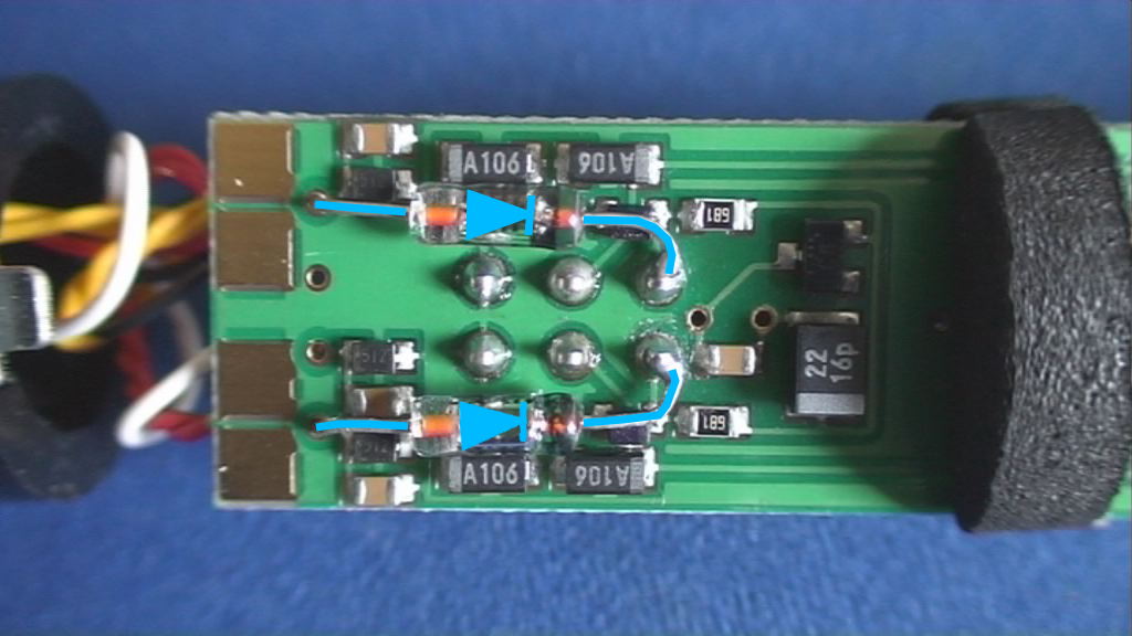
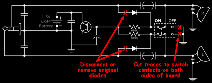
Germanium diodes have a lower forward voltage drop, about 0.2-0.3V compared to 0.6-0.7V. But instead of removing the existing diodes and possibly damaging the board, the germanium diodes can be added in parallel. This must be done carefully, using a soldering iron with a fine tip. The anode lead is soldered to a hole contact on the board, and the cathode lead (usually marked with a line on the diode) is soldered directly to the switch pin.
The circuit diagram shows where I added the 1N60 germanium diodes. The switch is shown horizontally flipped to simplify the diagram (the "off" side is towards the cable in the microphone). Not all filter capacitors are shown (some are paired):
These photos show the open microphone and exactly where the 2 germanium diodes were added:
1.2 Modification Results
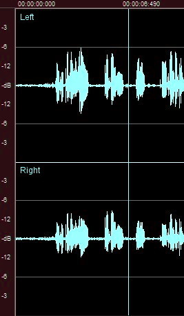
These audio samples were taken via firewire from the camcorder. Both results are very near voice recordings (from the left side, with some background noise) running only on plug-in power, with no battery in the microphone. The first results are from the original microphone, and the second results are after the modification:
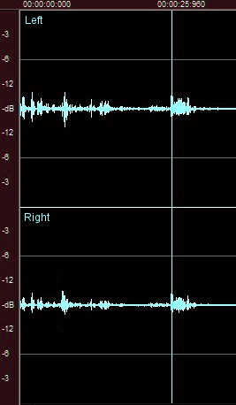
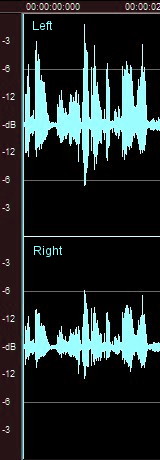
Original Audio Technica PRO24-CM
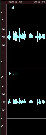
Modified Audio Technica PRO24-CM
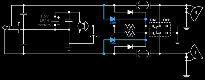
I changed the ON/OFF switch to a BATTERY switch, completely separating the battery feed and its low impedance from the plug-in power. The microphone now runs on plug-in power when the switch is OFF. It was dumb to require turning on the battery for plug-in power use anyway!The capsules now provide full sensitivity and high signal levels when switched to plug-in power, due to the very high load impedance. Resistors to ground decrease the load impedance and choose the desired sensitivity. I added a tiny switch for adjustable gain, which fits in the space at the end of the chassis where the cable is. It is a high quality ultra-miniature NKK Series G washable toggle switch G22AP, with gold plated contacts and terminals. The thin metal bracket and the rubber foam under it hold the switch in place without any glue:
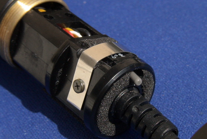
2.1 DetailsFirst the 2 switch hole contacts on the OFF side were disconnected from ground by cutting the traces to the holes on both sides of the board, and the original diodes were disconnected. Unfortunately the switch must be removed temporarily in order to cut the traces to ground beneath it, making this modification difficult with a high risk of damage for those without soldering skills or proper equipment:
My 1N60 germanium diodes were then connected to the switch pins on the OFF side instead (this is the opposite end of the switch, compared to the first modification).
The additional switch provides adjustable gain. The 10K resistors were chosen to reduce the very high gain to roughly match the volume of the internal camcorder microphone. About 1.5K for low gain was chosen to record in loud environments, but with higher signal levels compared to the very weak output of the original layout.
It is better to keep the high gain resistor hardwired and simply add the resistor for low gain in parallel to choose low gain. This prevents the gain from shortly jumping to maximum when there is no contact to any resistor during switching. In this case the low gain resistor would be 1.8K instead of 1.5K to account for the resulting parallel impedance (1/RLOAD = 1/RHIGH + 1/RLOW). I used matched metal film resistors with less than 1% tolerance:
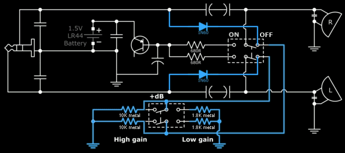
A single throw switch can be used instead of the dual throw switch shown above.
2.2 Modification Results
These samples of very near voice recordings (from the left side, with some background noise) show the gain of this modification using the chosen resistors with the battery switch off, running on plug-in power.The 1st example shows the high gain setting, the 2nd example shows the low gain setting, and the 3rd example shows the signal level of the internal camcorder microphone in comparison:
When the battery switch is turned on and the microphone runs on battery power, an additional setting is provided where the amplitude is similar to the first modification with plug-in power.
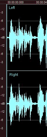
PRO24-CM high gain
PRO24-CM low gain
Internal microphone
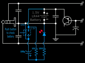
A tiny button with two way contacts, a capacitor (100µ), 2 resistors (150 and 10K) and a small red LED can check the battery state with a brief flash when its voltage has not gone below about 0.8V. The circuit doubles the voltage shortly to drive the LED. I tested the circuit but did not add it because I am using plug-in power without a battery.The button is shown not pressed, in which case the capacitor is charged through the 10K resistor. When the button is pressed, the minus pole of the capacitor is connected to 1.5V instead of ground, which doubles the effective voltage of the charge and drives the LED briefly until the capacitor is discharged: